Home › Guides › Bevel gear strength
Bevel gear strength: ISO 10300 safety factors explained
A bevel gear pair can look right, mesh without interference and still wear out or break in service. ISO 10300 is the standard that says whether it will carry its load: two safety factors, one for the tooth flank and one for the tooth root. This guide explains what they mean, what the recommended minimums are, and - measured on one pair - which design choices move them most.
Two ways a bevel tooth fails
Pitting is fatigue of the flank surface. Where two teeth roll and slide against each other the contact stress is high, and after enough cycles small pieces of the surface break out. It starts slowly and grows. ISO 10300-2 rates it from the contact stress σH.
Tooth root breakage is bending fatigue. Each tooth is a short cantilever loaded once per revolution, and the stress peaks in the root fillet on the tension side. A crack there runs through the tooth and the tooth breaks off. ISO 10300-3 rates it from the root stress σF.
ISO 10300-1 supplies what both have in common - the forces and the factors for how unevenly the load arrives: KA for the machine, Kv for the speed and accuracy, Kβ for the spread across the face and Kα between teeth. The strength of the material comes from ISO 6336-5.
What a safety factor is
For each gear and each mode, the standard compares the stress the tooth may take for the required life with the stress it actually gets:
| Flank (pitting) | Root (bending) | |
|---|---|---|
| Actual stress | σH | σF |
| Permissible stress | σHP | σFP |
| Safety factor | SH = σHP / σH | SF = σFP / σF |
A factor of 1.25 means the tooth could take a quarter more stress before reaching its permissible value. The permissible stress already contains the life: it is the material's endurance limit adjusted for the number of load cycles, the lubricant, the surface and the size. The pinion and the wheel are rated separately, and the designer shows the lower of the two against its minimum.
The recommended minimums
| Straight bevel | Spiral bevel | |
|---|---|---|
| SH,min (pitting) | 1.0 | 1.0 |
| SF,min (bending) | 1.5 | 1.3 |
These are the values ISO 10300-1:2014 clause 5.2 gives for supplied gears, with the note that the actual values are to be agreed between supplier and customer. A straight bevel here means a mean spiral angle of 5° or less. The root is asked for more than the flank for the usual reason: pitting develops gradually and tends to announce itself with noise, while a broken tooth stops the machine at once.
Why the two respond differently to load
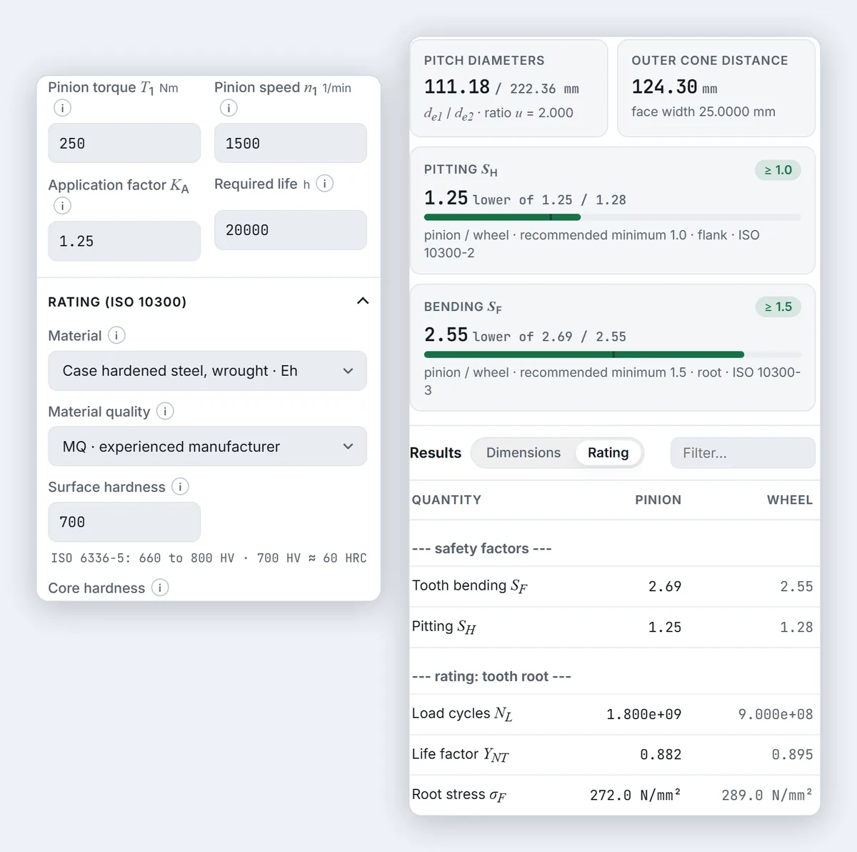
Contact stress grows with the square root of the load; root stress grows in proportion to it. So when the torque goes up, SF falls much faster than SH. Measured on a 20/40 straight pair, mmn 5 mm, face width 25 mm, at 1 500 min-1 (the example from how to design a bevel gear pair):
| Pinion torque | SH | SF |
|---|---|---|
| 125 Nm | 1.66 | 4.50 |
| 250 Nm | 1.25 | 2.55 |
| 375 Nm | 1.03 | 1.73 |
| 500 Nm | 0.89 | 1.31 |
Doubling the torque from 250 to 500 Nm roughly halves SF but takes SH down only by about √2. The ratios are not exact because the dynamic factor changes a little with the load. Two practical consequences: a large SF next to a modest SH is normal for a hardened pair, not a sign of over-design; and a pair that fails on pitting needs more than a little extra size to recover, because the flank gains only with the square root.
What moves them most
The same pair at 250 Nm - KA 1.25, case hardened steel at 700 HV, quality MQ, accuracy grade B6, 20 000 h - with one input changed at a time. The base gives SH 1.25 and SF 2.55.
| Change | SH | SF |
|---|---|---|
| Module mmn 4 / 6 mm | 1.00 / 1.49 | 1.66 / 3.53 |
| Face width 20 / 30 mm | 1.12 / 1.36 | 2.06 / 3.02 |
| Material quality ML / ME | 1.08 / 1.37 | 1.87 / 3.15 |
| Hardness 660 / 800 HV | 1.25 / 1.25 | 2.55 / 2.55 |
| Nitrided steel, 750 HV | 1.02 | 2.54 |
| Induction hardened, 560 HV | 0.98 | 2.20 |
| Through hardened alloy steel, 300 HV | 0.60 | 1.89 |
| Application factor KA 1.0 / 1.75 | 1.39 / 1.06 | 3.14 / 1.85 |
| Accuracy grade B4 / B8 | 1.26 / 1.17 | 2.63 / 2.24 |
| Speed 3 000 min-1 | 1.20 | 2.33 |
| Life 2 000 / 100 000 h | 1.34 / 1.18 | 2.67 / 2.46 |
What the table says:
- Size first. The module moves both factors furthest; the face width helps too, within the limits of 0.30 Re and 10 met.
- Material type and quality next. Case hardening gives the flank the most; a through hardened pair of the same size falls well short on pitting. Within one material the quality grade matters - ML, MQ and ME are the standard's grades of how well the material and its heat treatment are controlled.
- More hardness is not always more strength. Across the 660–800 HV band the designer accepts for case hardened steel, the permissible stresses it reads from ISO 6336-5 are the same, and so are the safety factors.
- Be honest about KA. It covers the shocks of the driving and the driven machine, and it changes the result as much as a module step. ISO 10300-1 has a guidance table; a uniform motor driving a machine with light shocks is 1.25.
- Accuracy, speed and life matter less here - up to about a tenth each - though at higher speeds the accuracy grade counts for more through the dynamic factor.
A spiral bevel of the same outer size is another lever; on a 20/40 pair of 100 and 200 mm pitch diameters it raised SH from 1.11 to 1.35 - see straight vs spiral bevel gears.
When a factor is too low
- SH below 1.0: a larger module or face width, a case hardened material, a better quality grade, or a spiral pair.
- SF below its minimum: a larger module helps most; a larger root fillet (a larger cutter edge radius) and a profile shift that balances the pinion and wheel roots help too.
- Check the inputs before the geometry: an application factor, a life or a speed that is higher than the machine really needs costs size for nothing.
The rating also depends on inputs that are easy to leave at their defaults: the lubricant viscosity, the surface roughness of the flank and the root, how the gears are mounted, the crowning and the contact pattern. The designer shows each with the value it uses, so they can be set to match the real gearbox.
Rate your own pair and see both factors against their minimums.
Open the designerQuestions
What is a good safety factor for bevel gears?
ISO 10300-1:2014 clause 5.2 recommends at least 1.0 against pitting (S_H) and at least 1.5 against tooth root breakage (S_F) for straight bevel gears, 1.3 for spiral bevel gears, with the final values to be agreed between supplier and customer.
Why is the bending safety factor so much larger than the pitting one?
Root stress grows in proportion to the load but contact stress only with its square root, and hardened steels are strong in bending. On a case hardened pair S_F is often twice S_H; pitting is usually the limit.
Does ISO 10300 cover spiral bevel gears?
Yes. ISO 10300 rates straight, spiral and zerol bevel gears and hypoid gears; the designer rates straight and spiral pairs with it and marks each pair's own minimums.
Does a harder case hardened steel give a higher safety factor?
Not across the whole range. For case hardened steel the permissible stresses the designer reads from ISO 6336-5 are the same from 660 to 800 HV, so the safety factors do not change; the material quality grade (ML, MQ, ME) does change them.