Home › Guides › How to design a bevel gear
How to design a bevel gear pair, step by step
A bevel gear pair is decided by a short list of choices - the ratio, the tooth numbers, the size, the face width and the material - and each one is limited by the others. This guide goes through them in the order that works, and ends with a worked example you can open in the designer.
1. Shaft angle, ratio and tooth numbers
Start from what the machine fixes: the angle between the two shafts, Σ (90° in most drives), and the speed ratio u = z2/z1. The ratio sets the two pitch angles - for a right-angle pair the pinion's is simply tan δ1 = z1/z2, so a 20/40 pair has δ1 = 26.565° and δ2 = 63.435°.
The pinion's tooth number is the choice with the most consequences. Few teeth make a small pinion but a weak, easily undercut one. ISO 23509 suggests how the working depth is shared between pinion and wheel (Table C.2) for straight bevel pinions of 12 or more teeth, and for spiral bevel pinions down to 6; below 12 on a straight bevel you have to set the profile shift yourself. For pinions of 12 or 13 teeth the standard recommends a 25° pressure angle instead of 20° (C.2.2). Many designers also avoid a common factor between the two tooth numbers, so that every pinion tooth meets every wheel tooth in turn and wear evens out.
2. Straight or spiral
Straight teeth are simpler to make and put no thrust towards the apex; spiral teeth run more smoothly and carry more for the same size. If the pair runs fast, has to be quiet or has to be compact, the spiral bevel usually wins. The differences, with numbers for one pair designed both ways, are in straight vs spiral bevel gears.
3. Module and size
The module sets the size of the teeth, and with the tooth numbers the size of the pair: the pinion's pitch diameter at the heel is de1 = z1 · met. Two modules are in use and it matters which one a catalogue or drawing means:
- met, the outer transverse module, at the heel - where a straight bevel is usually dimensioned;
- mmn, the mean normal module, at mid-face and normal to the tooth - the one ISO 23509 works in, and the natural one for a spiral bevel.
For the same pair they differ by the face width and, on a spiral bevel, by the spiral angle as well; on the 20/40 pair below, a mean normal module of 5 mm is an outer module of 5.559 mm. The module that is enough follows from the torque, so pick one from the space available and let the strength check in step 7 confirm or change it.
4. Face width
A wider face carries more load, but a bevel tooth tapers towards the apex, and a face that is too wide gives a toe too small to cut well and a pattern that is hard to keep centred. ISO 23509 Annex B.6 gives the usual limit: no more than 30 % of the outer cone distance Re, and no more than 10 met, whichever is less. The designer warns when either is exceeded.
5. Tooth profile, depth and profile shift
The tooth is generated by a basic rack - ISO 53 profiles A to D for a straight bevel, 20° pressure angle as standard - and its depths follow ISO 23509: an addendum factor of 1.0 and a dedendum factor of 1.25 on the mean normal module. The pinion is then given a positive profile shift and the wheel the same negative one (the "long and short addendum"), which makes the pinion's teeth longer and stronger and keeps them clear of undercut. ISO 23509 Table C.2 suggests the amount from the ratio; Clause 8 gives the range within which neither member undercuts. The designer uses both, and shows the teeth at each shift when you open the profile shift's help.
The basic rack's fillet radius becomes the cutter's edge radius, which shapes the root: type C (0.25 m) is the default, type A (0.38 m) the strongest root - if the slot at the toe has room for it.
6. Backlash and accuracy
A pair needs a little play so it does not bind under heat and tolerances. The designer takes the minimum normal backlash from JIS B 1705, or from ISO 23509 Table C.3 if you prefer, and removes it from the tooth thickness of both members. An accuracy grade (JIS B 1704, B2 to B11) adds the upper limit and the pitch tolerance the strength check reads.
7. Strength check
ISO 10300 rates a bevel pair for two failures: pitting of the flanks and breakage of the tooth root. Enter the pinion torque and speed, the application factor (ISO 10300-1 Table C.1 gives typical values for the driving and driven machine), the required life and the material. The result is a safety factor for each:
- pitting, SH, recommended at least 1.0;
- tooth root, SF, recommended at least 1.5 for a straight and 1.3 for a spiral bevel (ISO 10300-1, 5.2).
If a factor falls short, the usual cures are a larger module, a wider face (within step 4), a harder or better-grade material, or a spiral bevel instead of a straight one.
8. From numbers to a 3D model
Once the numbers hold, look at the pair: the axial section with the dimensions you pick, the tooth section at the heel and the mean point, and a 3D preview in the browser. The STEP export then writes exact solids of the pinion, the wheel and the pair in mesh, ready for any CAD program - see bevel gears in SolidWorks, Fusion 360, Inventor and FreeCAD.
Worked example
A right-angle straight bevel pair, ratio 2, run at 1 500 min-1 with a pinion torque of 250 Nm, an electric motor driving a machine with light shocks.
| Choice | Value | Why |
|---|---|---|
| Tooth numbers | 20 / 40 | ratio 2; 20 pinion teeth is inside Table C.2 and clear of undercut |
| Module | mmn 5 mm | = met 5.559 mm; de1 111.18 mm, de2 222.36 mm |
| Face width | 25 mm | under 0.30 Re = 37.3 mm and 10 met = 55.6 mm |
| Profile shift | xhm1 +0.435 | ISO 23509 Table C.2, inside the Clause 8 range |
| Load | 250 Nm, KA 1.25 | ISO 10300-1 Table C.1: uniform driver, light shocks at the driven machine |
| Material | case hardened, 700 HV | ISO 6336-5, quality MQ; accuracy grade B6 |
| Result | SF 2.55, SH 1.25 | lower of pinion and wheel; both above the minimums |
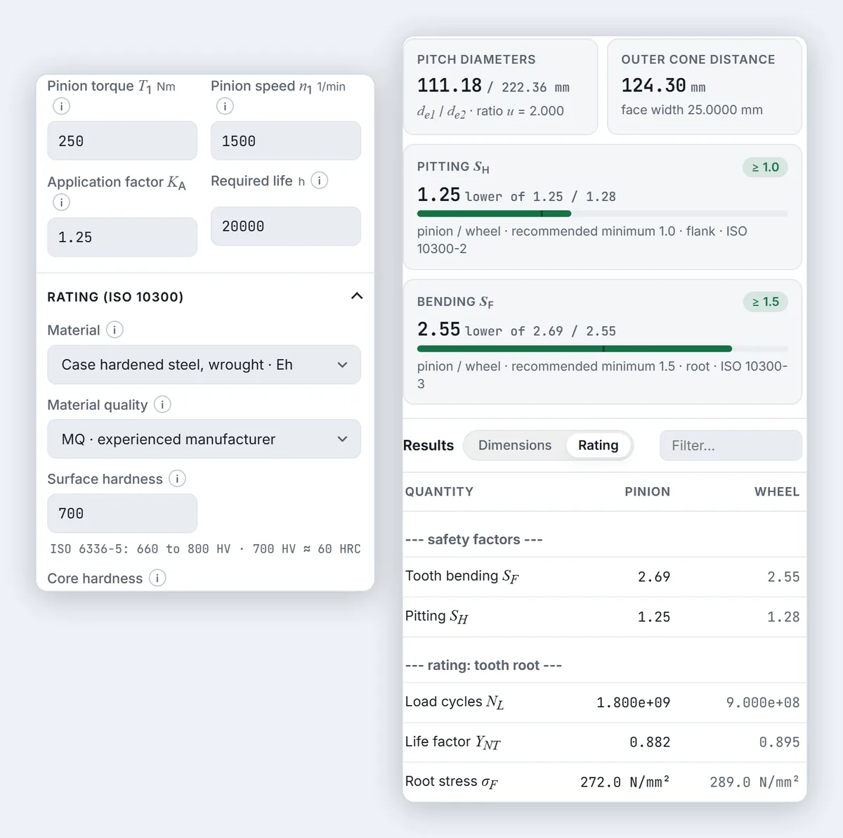
The root has margin to spare and pitting is the limit, so if the pair had to be smaller the place to look is the flank - a harder material or a spiral bevel - rather than the module.
Open this example in the designer and change it.
Open the exampleQuestions
What is the minimum number of teeth for a bevel pinion?
ISO 23509 suggests the profile shift for straight bevel pinions of 12 or more teeth and for spiral bevel pinions down to 6. Below that there is no suggestion, and small pinions need a larger pressure angle or a profile shift chosen by hand to stay clear of undercut.
How wide should the face of a bevel gear be?
ISO 23509 Annex B.6 gives no more than 30 % of the outer cone distance and no more than 10 times the outer module, whichever is less.
What safety factors should a bevel gear have?
ISO 10300-1 recommends at least 1.0 against pitting, and against tooth breakage at least 1.5 for a straight and 1.3 for a spiral bevel gear.