ISO 10300
Gear strength calculations
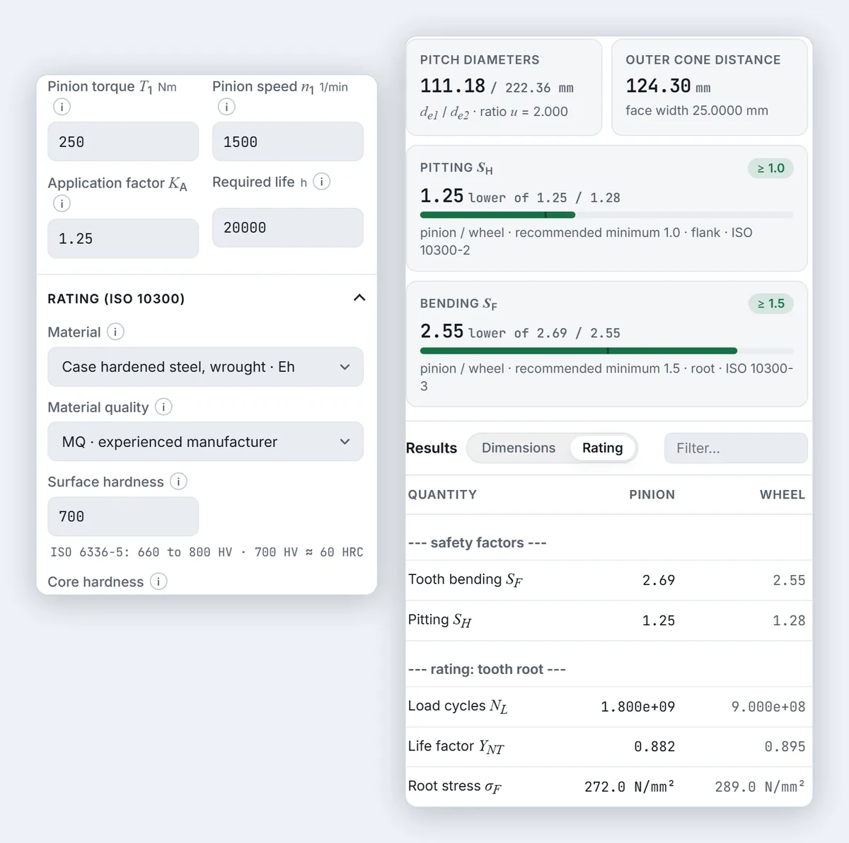
Pitting and tooth-root safety factors, updated as you type.
ISO 23509 · ISO 10300 · STEP · mm / inch
Straight and spiral bevel gear pairs to ISO 23509, rated to ISO 10300, in millimetres or inches (diametral pitch). Exact 3D STEP files for any CAD program — and every dimension names the clause it came from.
Free to use. A STEP file asks you to sign in with Google, and because each build is CPU-heavy an account may generate 3 a day.

ISO 10300
Pitting and tooth-root safety factors, updated as you type.
Interactive input
Every input comes with its figure or table. Click a value to use it.
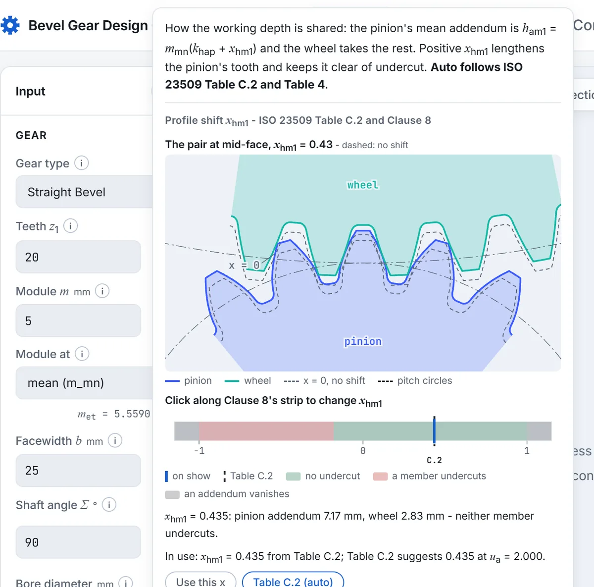
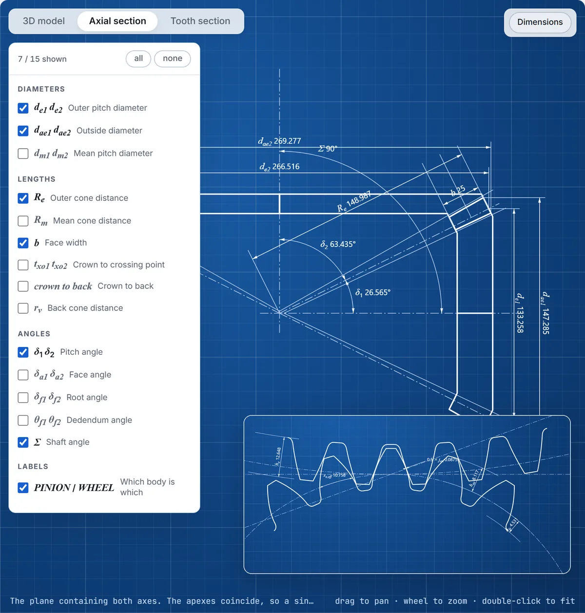
2D preview
Redrawn with every change. Pick the dimensions you want to see.
PDF report
Dimensions, safety factors and loads, ready to file with the drawing.

STEP export
Pinion, wheel and pair, cut the way a generating machine cuts them — written in millimetres or inches.

bevel_z20x40_m5_pinion.step
bevel_z20x40_m5_wheel.step
bevel_z20x40_m5_pair.step
bevel_z20x40_m5.txt
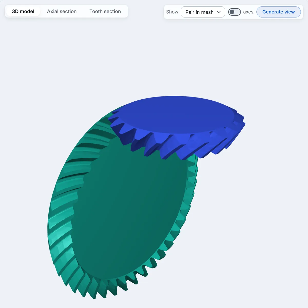
3D preview
Turn and zoom it in the browser. No account needed.
The spiral bevel geometry reproduces ISO 23509's worked example F.2 - its taper angles to 0.0001 degrees - and the load rating is held table by table to ISO/TR 10300-30 Sample 1, the standards committee's own worked example. Where a standard leaves something open, the page says so rather than filling it in silently. If a number disagrees with your own calculation, the disagreement is checkable: write to info@bevelgeargenerator.com.
Yes. The dimensions, the drawings, the 3D preview and the load rating are open to everyone without an account. Generating a STEP file builds both solids on the server, so it asks you to sign in with Google first, and each account has a daily allowance, shown beside the button.
ISO 23509 for the geometry of straight and spiral bevel gears, the ISO 53 basic rack for the generating tool, JIS B 1705 or ISO 23509 Table C.3 for backlash, and ISO 10300 method B1 with ISO 6336-5 allowable stresses for the load capacity of straight and spiral bevel pairs. The guides go through the design step by step.
Yes. The STEP files are exact 3D solids of the pinion, the wheel and the pair in mesh, and open in any CAD program that imports STEP — SolidWorks, Inventor, Fusion 360, CATIA, NX, FreeCAD and others — ready for a drawing, an assembly or CAM.
Yes. The mm / in switch in the top bar puts the designer in inches: the module is entered as the diametral pitch P = 25.4 / m, lengths in inches, torque in lbf·in, stresses in psi and oil viscosity in cSt, and the STEP files, STL and dimension report are written in inches. The PDF reports stay in millimetres, because the ISO formulas they quote are written for millimetres.
STEP files of the pinion, the wheel and the pair in mesh; STL if you ask for it; a plain-text dimension report; and a summary report as PDF with the dimensions and the safety factors.
Hypoid gears, face-hobbed spiral bevels and internal bevel gears are not generated, the teeth carry no crowning, and there is no loaded tooth contact analysis or scuffing rating.
How to design a bevel gear pairStraight vs spiral bevel gearsBevel gear terminologyBevel gears in CADMiter gearsBevel gear strength (ISO 10300)Minimum teeth and undercut
The designer opens on a working pair; change the teeth and the module and every figure follows.
Open the designer